One of the most expected features of HTML5 was the introduction of the canvas element, allowing to draw graphics on it. This tutorial will show how to draw 3D figures on it, but starting from the very beginning, in order to understand what we are actually doing.
As it is an HTML example, we won’t need any web server or back-end language installed in our machine, just a web browser.

For this example, the following browsers have been used for testing:
- Chromium 56.0.2924.76.
- Firefox 52.0.1.
- Opera 44.0.
Table Of Contents
1. The canvas element
2. Introducing the WebGL
2.1. Understanding WebGL
2.2. Initializing WebGL
2.3. 2D drawing
3. Three.js
3.1. 3D rotating cube
3.2. The code
4. Summary
5. Download the source code
1. The canvas element
Before diving into the 3D animations, we need to understand the element it relies on: the canvas.
The canvas element was one of the most expected novelties of HTML5. This element allows us to draw dynamically images in a webpage, usually done with JavaScript in combination with the canvas API.
As said, the element we have to use is canvas. So, something like the following would be enough to start:
1_canvas.html
<!DOCTYPE html>
<html>
<head>
<meta charset="utf-8">
<title>Canvas example</title>
<style>
#wrapper {
width: 60%;
margin: 0 auto;
text-align: center;
}
#canvas {
border: 1px solid black;
}
</style>
</head>
<body>
<div id="wrapper">
<h2>Canvas example</h2>
<canvas id="canvas" width="500" height="300"></canvas>
</div>
</body>
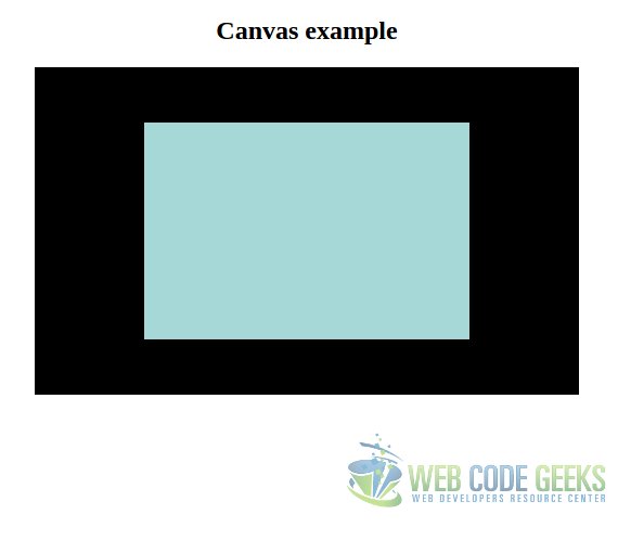
</html>This will render a white canvas in the browser of 500×300 (with the black border set with the CSS). Nothing very exciting.
But, now that we have our canvas, we can draw on it. Let’s see how to draw some simple rectangles with JavaScript to see the most elemental canvas functions.
1_canvas.js
document.addEventListener('DOMContentLoaded', function(event) {
    var canvas = document.getElementById('canvas');
    var context = canvas.getContext('2d');

    if (context) {
        context.fillRect(0, 0, 500, 300);
        context.fillStyle = '#a5d8d7';
        context.fillRect(100, 50, 300, 200);
    }
});
PD: do not forget to include the script in the HTML page:
<!-- ... -->
<head>
    <!-- ... -->
    <script src="1_canvas.js"></script>
    <!-- ... -->
</head>
<!-- ... -->
The first thing we do is to bind the piece of code that manipulates the canvas to the DOMContentLoaded listener, since we have to be sure that the elements are loaded before we access them.
Then, we get the canvas object from the DOM. But, for drawing on it, we need to get the render context of the canvas, in this case, still the 2D context. This context offers the method for drawing in the canvas.
The fillRect method fills the canvas from the starting X, Y coordinates, to the ending X, Y ones, with the given color. So, for this instruction:
context.fillRect(0, 0, 500, 300);
Would fill the canvas, in the X axis, from the point 0 to 500 (first and third parameters, respectively); and in the Y axis, from the point 0 to the 300 (second and fourth parameters, respectively). As any color was set, it will be filled with the default one, black.
After that we do the same, but setting a different color for the fill, and for another coordinates.
The result is shown in the following image:
2. Introducing the WebGL
After seeing how works the canvas element at it most basic level, it’s time to introduce WebGL.
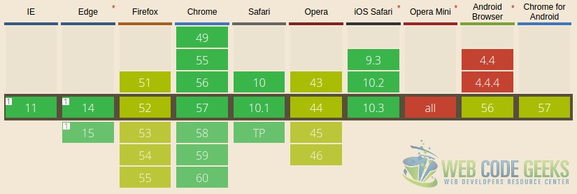
For the 3D animations with the canvas, we don’t have to get the 3d context, as you may have thought. Instead, we have to get the webgl context, which is supported, at least partially, by every modern web browser (see next image).
2.1. Understanding WebGL
WebGL is not just about drawing some specific pixels on a canvas. In order to draw an image, we have to define a spatial vector that represents the image, which will be converted, using the OpenGL specification, to its pixel representation.
This may sound scary, and that’s why we must understand the whole process in order to write WebGL applications.
2.1.1. Coordinate system
Being a three-dimensional system, we have three axes: X, Y, and Z, being the last one the depth. In WebGL, the coordinates are limited to (1, 1, 1) and (-1, -1, -1).
We have to understand that, when we define figures, we don’t have to think in pixels, but in vector representations in a coordinate system within a cartesian system.
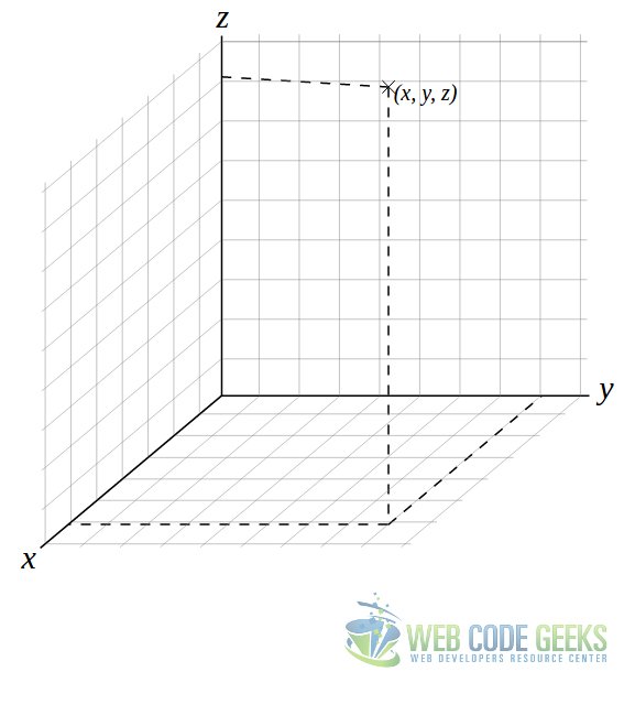
Imagine the system like in the image above (that’s actually what we are going to deal with). The drawn point, (x, y, z), is represented by the coordinates in the X, Y and X axes.
Now let’s suppose that we want to build a cube, and that the coordinates commented above are for one of the bounds of the WebGL system. That coordinate would be (1, 1, 1). That means that we have just one of the corners of the cube, and a cube has 8 corners. So we need several more coordinates.
The other coordinates would be (1, 1, -1), (1, -1, -1), (1, -1, 1), (-1, -1, -1), (-1, 1, -1), (-1, 1, 1) and (-1, -1, 1). Tracing the vortexes between these coordinates, we would define the volume of the cube.
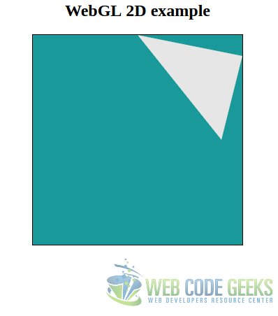
This might be easier to understand in the second dimension, just with the X and Y axes, where the underlying principle is the same. Suppose three coordinates, e.g. (0.8, 0), (0, 1) and (1, 0.8). With this vortexes, we would draw a triangle like in the following image.
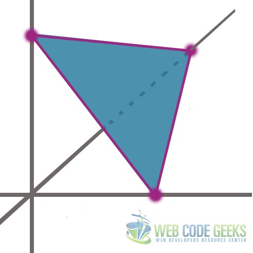
As said, the principle is the same as for the three-dimensional figures with a third axis, but easier to understand if the previous example was confusing.
2.1.2. Shaders
The shaders are pieces of code that are executed in the GPU for representing each pixel that will make up the final scene. There are two types of shaders:
- Vertex shader: this one, as you will probably have already guessed, is the responsible for manipulating and representing the vertexes, calculating the texture and the position of each vertex, among other things.
- Fragment shader: this one manipulates each pixel that compose the area bounded by the vertexes.
Note: these pieces of code are not written in JavaScript, but in script type known as x-shader/x-vertex. We will see it later.
2.2. Initializing WebGL
Knowing that there are some browsers with just partial support, we should implement a fallback for the browser that do not offer full support. This is actually very easy. The following script will tell us if our browser is compatibly or not with WebGL:
var webgl = canvas.getContext('webgl')
    || canvas.getContext('experimental-webgl');

if (!webgl || !(webgl instanceof WebGLRenderingContext) ) {
    alert('Failed to get WebGL context.');
} else {
    alert('Great, your browser supports WebGL.');
}
As you can see, it’s almost as same as with the 2D context. But, in this case we try to get the main WebGL, or, the experimental one, if the first one fails (i.e. returns false). After, we check if the experimental WebGL retrieval also failed, checking also that effectively the returned object is an instance of the WebGLRenderingContext.
2.3. 2D drawing
Yes, we have already seen how to draw in 2 dimensions, but that was with a different context, with the aim of understanding the basics of the canvas element.
The previous obvious step to the 3rd dimension, is the 2nd one. Starting directly drawing in 3D, may result in not actually understanding the functioning of the WebGL.
So, let’s draw a triangle as in the previous picture.
The following code will show our script at the higher level, just showing the functions we have created for rendering the figure.
var vortexes = [
    0.8, 0.0,
    0.0, 1,
    1, 0.8
];

webgl = getWebGL();

if (webgl) {
    initWebGL(webgl, vortexes);

    var vertexShader = createVertexShader();
    var fragmentShader = createFragmentShader();

    var shaderProgram = createShaderProgram(webgl, vertexShader, fragmentShader);

    transformCoordinatesAndSet(webgl, shaderProgram);

    drawArrays(webgl);
}
As you can see, we have just: defined the vortexes of the triangle (the same values as used for the picture of the previous section), init the WebGL, create the vertex and fragment shaders, create the shader “program” from the shaders, set the specified coordinates, and draw the arrays.
So, the full script would be:
2_webgl.js
document.addEventListener('DOMContentLoaded', function(event) {

    /**
     * Inits the WebGL or returns false if it couldn't be loaded.
     */
    function getWebGL() {
        var canvas = document.getElementById('canvas');
        var webgl = canvas.getContext('webgl')
            || canvas.getContext('experimental-webgl');

        if (!webgl || !(webgl instanceof WebGLRenderingContext)) {
            return false;
        }

        return webgl;
    }

    /**
     * Creates the vertex buffer, binds it, passes the vortex data to it,
     * and sets the color.
     */
    function initWebGL(webgl, vortexes) {
        var vertexBuffer = webgl.createBuffer();

        webgl.bindBuffer(webgl.ARRAY_BUFFER, vertexBuffer);

        webgl.bufferData(
            webgl.ARRAY_BUFFER,
            new Float32Array(vortexes),
            webgl.STATIC_DRAW
        );

        webgl.clearColor(0, 0.5, 0.5, 0.9);

        webgl.clear(webgl.COLOR_BUFFER_BIT);
    }

    /**
     * Creates the vertex shader object from the source code defined in
     * 2_vertex_shader.js.
     */
    function createVertexShader() {
        var vertexShader = webgl.createShader(webgl.VERTEX_SHADER);
        webgl.shaderSource(vertexShader, vertexCode);
        webgl.compileShader(vertexShader);

        return vertexShader;
    }

    /**
     * Creates the fragment shader object from the source code defined in
     * 2_vertex_shader.js.
     */
    function createFragmentShader() {
        var fragmentShader = webgl.createShader(webgl.FRAGMENT_SHADER);

        webgl.shaderSource(fragmentShader, fragmentCode);
        webgl.compileShader(fragmentShader);

        return fragmentShader;
    }

    /**
     * Create and attach the shader programs from the shader compiled objects.
     */
    function createShaderProgram(webgl, vertexShader, fragmentShader) {
        var shaderProgram = webgl.createProgram();

        webgl.attachShader(shaderProgram, vertexShader);
        webgl.attachShader(shaderProgram, fragmentShader);
        webgl.linkProgram(shaderProgram);
        webgl.useProgram(shaderProgram);

        return shaderProgram;
    }


    /**
     * Gets and sets the coordinates associating the compiled shader programs
     * to buffer objects.
     */
    function transformCoordinatesAndSet(webgl, shaderProgram) {
        var coordinates = webgl.getAttribLocation(
            shaderProgram,
           'coordinates'
        );

        webgl.vertexAttribPointer(
            coordinates,
            2,
            webgl.FLOAT,
            false,
            0,
            0
        );

        webgl.enableVertexAttribArray(coordinates);
    }

    /**
     * Draws the arrays.
     */
    function drawArrays(webgl) {
        webgl.drawArrays(webgl.TRIANGLES, 0, 3);
    }

    var vortexes = [
        0.8, 0.0,
        0.0, 1,
        1, 0.8
    ];

    webgl = getWebGL();

    if (webgl) {
        initWebGL(webgl, vortexes);

        var vertexShader = createVertexShader();
        var fragmentShader = createFragmentShader();

        var shaderProgram = createShaderProgram(webgl, vertexShader, fragmentShader);

        transformCoordinatesAndSet(webgl, shaderProgram);

        drawArrays(webgl);
    }
});
Remember that we told before that the shaders were pieces that have to be compiled. Note that, in the code above, we haven’t defined fragmentCode (line 44) nor vertexCode (line 57). These are the pieces of code for the fragment, which we defined in separated files:
fragment_shader.js
var fragmentCode = `
    void main(void) {
        gl_FragColor = vec4(
            0.0,
            0.0,
            0.0,
            0.1
        );
    }`
;
vertex_code.js
var vertexCode = `
    attribute vec2 coordinates;
    void main(void) {
        gl_Position = vec4(
            coordinates,
            0.0,
            1.0
        );
    }`
;
PD: don’t forget to add the code to the HTML page:
<!-- ... -->
<head>
    <!-- ... -->
    <script src="2_fragment_shader.js"></script>
    <script src="2_vertex_shader.js"></script>
    <script src="2_webgl.js"></script>
    <!-- ... -->
</head>
<!-- ... --->
Wow, that was to much code for drawing a simple triangle, wasn’t it? Imagine for an animated 3D figure…
Fortunately, for doing this, we will use a library that will make our lives easier.
3. Three.js
We have seen how to deal with WebGL at the lowest level. And perhaps, we got disappointed: too much work, too much code, for the simplest task.
As already commented, fortunately, there are libraries available for drawing 3D figures that will save much time, besides being easier. Probably the most known is three.js, which its simplicity is fascinating, more after dealing with native WebGL.
For using it, we just have to download the latest minified build (more than 500kb!). For this case, the version r84 has been used.
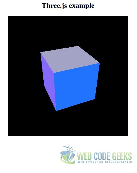
3.1. 3D rotating cube
Before seeing the code, let’s see what we are going to achieve. We will draw a 3D cube, which will rotate in both X and Y axes. The following image shows it, statically, but it will actually rotate!
3.2. The code
We will work in the same codebase. Just don’t forget to include the three.js library. The code for drawing the previous animated cube is the following:
3_three.js
document.addEventListener('DOMContentLoaded', function(event) {
    window.requestAnimationFrame = (function() {
        return window.requestAnimationFrame;
    })();

    function animateScene() {
        requestAnimationFrame(animateScene);

        cube.rotation.y += 0.02;
        cube.rotation.x += 0.01;

        renderScene();
    }

    function createCube() {
        var cubeMaterials = [
            new THREE.MeshBasicMaterial({color:0x2173fd}),
            new THREE.MeshBasicMaterial({color:0xd5d918}),
            new THREE.MeshBasicMaterial({color:0xd2dbeb}),
            new THREE.MeshBasicMaterial({color:0xa3a3c6}),
            new THREE.MeshBasicMaterial({color:0xfe6b9f}),
            new THREE.MeshBasicMaterial({color:0x856af9})
        ];

        var cubeMaterial = new THREE.MeshFaceMaterial(cubeMaterials);
        var cubeGeometry = new THREE.BoxGeometry(2, 2, 2);

        cube = new THREE.Mesh(cubeGeometry, cubeMaterial);

        return cube;
    }

    function startScene(cube) {
        var canvas = document.getElementById('canvas');
        render = new THREE.WebGLRenderer();

        render.setClearColor(0x000000, 1);

        var canvasWidth = canvas.getAttribute('width');
        var canvasHeight = canvas.getAttribute('height');
        render.setSize(canvasWidth, canvasHeight);

        canvas.appendChild(render.domElement);

        scene = new THREE.Scene();
        var aspect = canvasWidth / canvasHeight;

        camera = new THREE.PerspectiveCamera(45, aspect);
        camera.position.set(0, 0, 0);
        camera.lookAt(scene.position);
        scene.add(camera);

        cube.position.set(0, 0, -7.0);
        scene.add(cube);
    }

    function renderScene() {
        render.render(scene, camera);
    }

    var cube = createCube();
    startScene(cube);
    animateScene();
    renderScene();

});
Creating the cube
Creating the cube (line 15) is so simple. We just create an arraywhere we define each side (6 in total), specifying the material of each side, and the color of it.
Starting the scene
The function in line 33. For starting the scene, we also have to set the render and the camera.
For the render, we instantiate the THREE.WebGLRenderer class, set a clear color (black), define its dimensions (which are already defined in the canvas element in the HTML), and append it as a child to the canvas.
For the camera, in this case, we instantiate the THREE.PerspectiveCamera class, passing 2 parameters:
- The first parameter defines the visual field of the camera, in degrees. So, setting it to 45, would be like looking to the cube being in front of it.
- The second one is the aspect ratio. For this, generally, we will want to set the width of the element divided by the height. Otherwise, the image will look deformed.
Then, we set the camera in a certain position, we tell it to look at the position of the instantiated scene, and we add the camera to the scene. Finally, we can add the cube to the scene.
Animating the scene
For animating the scene (line 6), we have to do it requesting the animation frame to the browser. To it, we pass the function to be executed as callback, which is the one of animating the scene.
Rendering the scene
Rendering the scene consists just on calling the render method of the render object, passing the scene and the camera.
4. Summary
In this tutorial we have seen how to draw a 3D image (that also rotates), using the HTML5 canvas element and the three.js library, but, also seeing how to create graphics from the scratch, fundamental for understanding how does the WebGL and canvas work.
5. Download the source code
This was a tutorial of HTML5 3D canvas.
You can download the full source code of this example here: HTML53DTutorial

Near the end of 3_three.js, after animateScene() is called, renderScene() is called next. But animateScene() already calls renderScene() as its last instruction.
You clearly meant “vertices” where you’ve put “vortexes”.